
Electromagnetic Launch Modification
Project # 23-037 | Year 2 of 2
M. Cameron Hawkinsa, Russell Howea, James Majdanaca, Todd Warea,
Sarah Thomasb, Ty Ricec, Zach Shawa, Ivan Apontea, Dawson Wrighta
aNevada National Security Sites (NNSS), bLos Alamos Operations (LAO), cRemote Sensing Lab-Andrews (RSLA)
This work was done by Mission Support and Test Services, LLC, under Contract No. DE-NA0003624 with the U.S. Department of Energy, the NNSA Office of Defense Programs, and supported by the Site-Directed Research and Development Program. DOE/NV/03624–1902.
Abstract
This project is the first step in the development of a novel technology that could lead the Nevada National Security Sites (NNSS) towards a platform that would achieve projectile velocities with pulsed power instead of the explosive hazards (e.g. high explosives) that exist with the current Joint Actinide Shock Physics Experimental Research (JASPER) test facility. Originally, the project began as a collaboration between university and national laboratory contacts to develop a full-size system to pair with the C3 Launcher gas gun at NNSS North Las Vegas facility. However, due to unforeseen circumstances the project was replanned and a series of experiments of a benchtop system were conducted to prove the concept of using pulsed power to drive a piston, which can be used to compress gas to high pressures to accelerate a projectile to high velocities. This benchtop system consisted of three needed sub-systems: 1) Pulse Forming Network (PFN), 2) Electromagnetic launcher (EML), and 3) a pressure system to launch a projectile. Simulations and calculations were performed as well as Computer-Aided Design (CAD) models to specify parts, fabricate, and assemble the systems to evaluate each individually and then together as a final unit.
Background
During the first two and a half years of the project, NNSS partnered with university and national laboratory collaborators to develop a system that would pair with the C3 Launcher. The system was envisioned to compress gas in the pressure reservoir in a ratio of 1:3. Plans were to design and build a system that would achieve a maximum pressure of 9 ksi from an input pressure of 3 ksi.
NNSS’s primary contribution was in the design of the interfacing pressure components necessary to couple the EML to the C3 Launcher to propel the projectile down the launch tube, including simulation of the components and drawings needed for procurement of the components. These components were designed in such a way that they can adequately pair to the C3 Launcher but also follow similar functions to that of JASPER, so that a seamless integration can be implemented on that platform as well. These components were designed using simulations and hand calculations to ensure proper factor of safety for the pressure system, which included the pressure reservoir, barrel adapter, petal valve retainer, petal valve, and projectile. The team evaluated how these parts would pair together, considering O-ring sizing, bolt sizing, clearances, and necessary diagnostics such as pressure transducers and thermocouples. A study was undertaken to determine adequate stoppage of the projectile in the catch tank. We also designed and built the gas supply and vacuum supply system, developed the work control needed for high pressure and high voltage/pulsed power, and created leak test and operational procedures. A control system was designed and implemented into the platform that would interface with the gas supply system, launcher controls, and EML/PFN.
Technical Approach
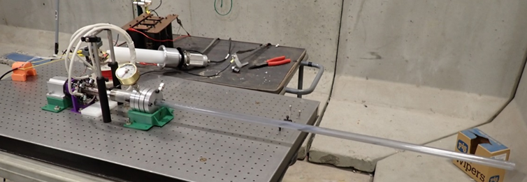
The full system was designed to mount to an optical table and alignment was carefully addressed by implementing certain components into the assembly. A linear plastic ball bearing was used to ensure the piston maintained alignment with the pressure reservoir. 3D-printed parts were used to mount the ball bearing, stator/ brush assembly, and petal valve retainer components to the optical table. An L bracket was placed at the rear of the plunger to prevent it from moving backwards due to any recoil forces. A bolt and washer assembly prevents the piston from moving too far forward.
Off the shelf parts were sourced and modifications were made to a set of four flanges to function as a petal valve retainer as well as a reducer into the launch tube. This allowed for flexibility in making any necessary changes to the profile of the reducer later during testing as well as to install and remove the petal valve. The first flange was connected to the pressure reservoir, which was designed to withstand the desired maximum pressure and to be long enough to allow for the desired piston stroke length. An O ring on the outer diameter of the plunger was used to create a seal between the plunger and reservoir. The barrel was attached to the last flange and allowed for insertion of the projectile into the system. All pressure components were evaluated to determine proper factors of safety for the system. This modular system allows for modifications or adaption which may be needed during troubleshooting of the system.
Considerable troubleshooting occurred during the build of the system. The trigger had to be isolated from the thyristor switches by using a pulse transformer to keep the low voltage logic and the high voltage load side isolated. We also saw a premature fall in the current before the peak, which was caused by mirror currents on the inner windings of the multi-layer coil. This was due to the wound coil changing shape during firing by collapsing. The solution was to fix the coil down in place so that it would not compress during firing. We also addressed friction issues with the mechanical components and realigned/modified the system to improve these issues. The brushes were also a source of troubleshooting, and we were able to modify the area of contact as well as the alignment to improve contact.
The full system shown in the figure was designed for up to 1,000 V (1kV) with a two stage PFN but was only tested up to 400V due to time and schedule constraints. The only available power supply with the necessary current required would not allow us to continue tests past 400V. In addition, the second set of capacitors was not included in the first rounds of testing due to time constraints on the project. With this in mind, the system running at 400 V and only on one PFN showed a 0.25-inch movement of the piston. To put this in perspective, this means that the system was running at only 20% of its total voltage capacity, equating to about 4% of the possible force for the preliminary proof of concept. With this small amount of voltage, the system was able to overcome friction and move the plunger.
Results and Technical Accomplishments
The team developed and designed a full system that when finally built and assembled has the potential to provide an alternative approach to traditional two stage gas gun technology. A benchtop system was used to demonstrate the concept on a small scale.
Conclusions and Path Forward
The team was successful in designing and building a system using pulsed power to move a piston forward. The functioning benchtop system will be further developed for use in pulsed power skillset development. More testing will be performed during the next year under programmatic space to test the final inductor value arrangement, reduce the weight of the piston, add a larger power supply, add the second PFN stage, and add the mechanical system for full system testing. This developed approach has the potential to create a platform able to launch projectiles at high velocities with a quicker, cleaner, and more efficient way to pressurize a chamber of gas.
Back to Accelerator Beam Science and Target Interactions Index