
Can Two Pulsed Power Sources of Different Source Impedance Drive the Same Non-Linear Load?
Project # 23-053 | Year 2 of 2
Zachary C. Shawa, Dawson Wrightb, Keegan Kelpb, Jacob Stephensb,
James Dickensb, Andreas Neuberb
aNevada National Security Sites (NNSS), bTexas Tech University
This work was done by Mission Support and Test Services, LLC, under Contract No. DE-NA0003624 with the U.S. Department of Energy, the NNSA Office of Defense Programs, and supported by the Site-Directed Research and Development Program. DOE/NV/03624–1910.
Abstract
With emerging solid-state topologies, interest has been generated in coupling these compact generators with more traditional pulsed power generators. There are a number of large Department of Energy (DOE) testbeds that utilize multiple generators of the same electrical characteristics, but none to the authors’ knowledge that allow for the coupling of solid-state sources. These emerging solid-state topologies would theoretically allow for wave-shaping of generator waveforms delivered to a load. These are of particular interest in drivers for non-linear loads that experience an impedance collapse or spike. Being able to provide a “kick,” improve pulse rise-time, or correct droop are a number of ailments that befall many systems driving non-linear loads. The goal of this study is to investigate the feasibility, and suggest any techniques, to the coupling of two sources that are of differing electrical characteristics to drive a non-linear load. After a literature review and electromagnetic simulation work, two methods have shown great promise in a feasible setup. This project was conducted in collaboration with Texas Tech University (TTU), who provided insight and research into developing and troubleshooting a solid-state pulsed power source and multi-pulse properties of magnetic cores, which are commonly used in these types of topologies.
Background
DOE testbeds such as Cygnus (2.7 MV staggered Marx), Dual Axis Radiographic Hydrodynamic Test (DARHT) 1 (pulse charged, tri-axial Blumlein pulse forming line), Z-Machine (36, 5.1 MV Marx generators), and Gemini (1 MJ, 140 kV Marx generator bank) are entering or have passed their 20th year of operation. The undertaking of constructing more modern machines such as Advanced Sensor Development (ASD) Scorpius or the next generation of Z is known to be costly and take a large amount of time due to project requirements, budget, and staffing. This ultimately motivates the study of taking well studied pulsed power generators and coupling solid-state sources to them, allowing for pulse shaping via modulation. In theory, refurbishment of these machines would allow for extended lifetime of the testbeds without the need to start over from scratch. These testbeds that use more traditional pulsed power generators have a relatively fixed or stiff waveform that cannot be varied. Allowing for operations to construct an ideal waveform or provide waveform flexibility would breathe new life into these machines and allow for new territory to be covered. After conducting a literature review, there is no semblance of this type of technique in literature to the author’s knowledge. All multi-generator sources used duplicates of the same source, which coalesce into a single load. Problems identified at the writing of the proposal for this project were the impedance matching of the two sources and protection/isolation of the supplemental source from the main source.
Technical Approach
Starting with first principles, this problem can be broken down into two ideal, pulsed sources that travel along a transmission line (T-Line) to an arbitrary load. One source outputs a pulse train, representing supplemental sources or sources whose primary function is wave shaping the signal from the prime source. Throughout this report, the terms prime and supplemental source will serve to designate the function of each generator in circuit models, theory, etc.
Constructive interference allows for the prime and supplemental waveforms to combine on the T-Line and be delivered to the load. A superposition of each generator’s waveform as well as the combined waveform was demonstrated. This first principle simulation proved fruitful in showing that basic theory agrees with the simple T-Line theory needed to make this technique a reality. However, throughout the course of the study there were major hurdles that were identified in the actual implementation of this technique.
To realistically carry out this technique, a form of coupling was applied to the overall system to establish the beginnings of electrical isolation from one source to another. Inductive coupling is used throughout literature for coupling multiple sources together in the form of Linear Transformer Drivers (LTDs) and Inductive Voltage Adders (IVAs).
Driving a 1:1 transformer as demonstrated lead to a simplified non-linear load with a fixed capacitance and variable load resistance. This load resistor simulated an overly simplified impedance collapse, to see how this affected the coupling of the two sources. Post impedance collapse showed that the supplemental source was still applying a pulse train to the load. This confirmed that it is possible for the supplemental source to ideally provide continual constructive interference, even during rapid impedance swings in the load. This leads one to the conclusion that variation of pulse formats in the supplemental source would also be seen during these impedance shifts.
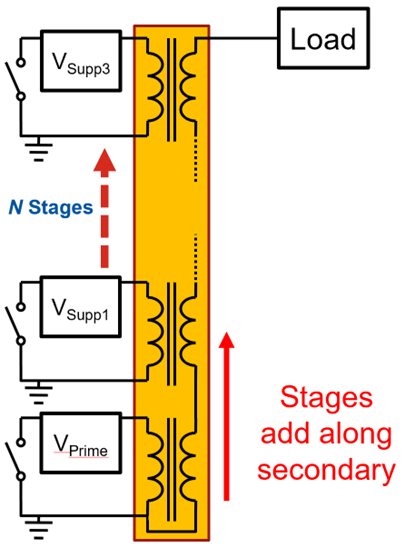
Finally, a method utilizing a LTD topology was studied with a single prime source and three supplemental sources driving a load with 250 kV and 50 kV each, respectively. Multiple stages drove individual inductors, which acted as the primary of a 1:1 transformer. Typically, these stages are mounted axially about a continuous, conductive stalk that acts as the secondary. This allowed for isolation between each stage while the signals experience constructive or destructive interference along the secondary line. The voltage seen at the load was non-ideal due to added transformer losses and coupling factors, yet still emphasized the potential of this topology as a viable path forward for future research.
Results and Technical Accomplishments
Two paths were identified (with a possible third) to move forward on the pulsed power coupling device. Under subcontract, TTU identified two solid-state generator topologies, an approximate budget, and performed initial characterization of magnetic materials that would be used in such sources.
Literature reviews were conducted by NNSS personnel and TTU to determine the best paths forward. The decision was made at the end of the feasibility study to design a system capable of coupling a traditional, small scale dense plasma focus (DPF) to a solid-state generator. We are currently working closely with the NNSS DPF group to gain insight on the intricacies of the plasma pinching action.
Conclusions and Path Forward
This study concluded that the path forward is viable, and there are several major questions that need to be answered. On the NNSS side of the project, the coupling device needs to provide adequate protection circuitry for the supplemental source to be protected from the prime source. Another alternative is to seek a third topology (currently in progress) that lends an intrinsically high isolation without the need for circuit components.
TTU and the NNSS have agreed on a solid-state generator topology to be used to drive a small DPF head and a subsequent path forward in order to successfully implement a multi-stage generator as a final product (for Year 2 of 2).
Back to Accelerator Beam Science and Target Interactions Index