
Multi-Modal Remote Vibrometer for Infrastructure Interrogation
Project #: 22-087 | Year 1 of 3
Steven Koppenjan,a David Baldwin,a Joe Mendez,a Paul Taylor,a Eric Larson,a Ebrahim Saberiniab
aSpecial Technologies Laboratory; bUniversity of Nevada, Las Vegas
Executive Summary
This project is to develop a next generation detection system to improve methods of remotely characterizing facilities of interest, and to increase standoff from hundreds of meters to multi-kilometer ranges. The multi-modal remote vibrometer (MMRV) for infrastructure interrogation combines active dual comb laser techniques, turbulence mitigation and micro-doppler radar. This effort will move laboratory bench scale Dual Comb Spectroscopy (DCS) techniques to the field and is directly related to the NNSA mission and treaty verification.
Description
In Year One, we assembled and modified the DCS MMRV and built a 3 GHz radar from existing radio frequency components and subassemblies. With the advice of Oak Ridge National Laboratory collaborators, these two systems were used to collect signals of vibrating surfaces in lab experiments. In partnership with the University of Nevada, Las Vegas (UNLV), transforms were investigated to best detect these vibrations. Several student interns assisted on the project during the summer by collecting data and testing target design.
The DCS MMRV was assembled by leveraging components (such as the laser) purchased for a separate SDRD project. Additional components that were necessary to provide the additional phase coherence required for DCS vibrometry were specified, purchased, and assembled. These were tested to replicate some prior work and provide a basis for developing the remote detection capability in year two. The radar with a high-performance signal sampler was used to record the analog data from the radar receiver. Two pairs of antennas (horns and flat panel) are used for data collection. A circular foam target lined with metal foil and an instrument that can vibrate it at a selected rate was used for the calibration tests. Software has been written for a real time visualization of the acquired data to include a time domain view and a spectrogram view, or a frequency domain versus time view. Scripts were written for a user to save raw data in different combinations of sampling rate, bit depth, and record length. Scripts have also been written for data processing and visualization of the calibration experiments. Six calibration experiments were performed with data acquired with different antenna types pointed at the vibrating target at varied distances. The measured Doppler shift was extracted from this data. The collected unprocessed data was then processed offline at the Special Technologies Laboratory and with our UNLV partner. This work will continue in FY 2023 with the combining of the measured lab data and comparison with data collected from Lawrence Livermore National Laboratory experiments, along with the development of extraction algorithms in parallel with collecting data under high turbulence conditions.
Conclusion
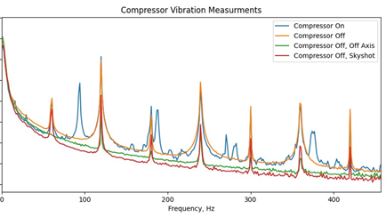
We have assembled a DCS MMRV using a new method to create combs that interleave the comb pairs on either side of the central wavelength, rather than using an Acousto-Optic Modulator to shift all of the combs, and to break degeneracy in the FFT. This design removes the requirement for phase locking multiple oscillators, which is a direct benefit for the vibrometry application that is dependent on the phase coherence of multiple sources with the benefit to reduce the bandwidth requirement of the receiver. The micro-Doppler radar was calibrated with a known test source (amplitude of displacement and frequency). One experiment was performed by pointing the radar at a building wall with vibrating equipment in the room on the other side. The system was able to measure, detect, and determine whether the equipment signals were off (no vibrations) or on (vibrations). This demonstrates the ability of this micro-Doppler system to detect and measure real-world vibrations in the presence of other vibrating signals.
We will continue development and application of signature extraction algorithms for each sub-system creating output files that can be used to develop the critical MMRV techniques. This data will allow us to modify our turbulence mitigation techniques for the DCS. We will collect data simultaneously with a laser doppler vibrometer to benchmark our system signal to noise ratio versus standard vibrometry.
Mission Benefit
The goal is to develop a multi-modal system for facility monitoring, including interior machinery, fans, generators, and pumps, and to correlate to remote sensing observables that are relevant to Patterns of Life. Given the physical motions being measured are highly correlated, we expect multi-modal processing of waveforms to produce higher fidelity than any single sensor technology, creating the next generation vibrometer. A successful end for the project would be the demonstration of a multi-modal vibrometer and resulting performance enhancement due to improved DCS sensitivity and data integration, compared to existing laser-based techniques for standoff structural vibrometry.
This work was done by Mission Support and Test Services, LLC, under Contract No. DE-NA0003624 with the U.S. Department of Energy. DOE/NV/03624–1607.
Return to Enabling Technologies for Autonomous Systems and Sensing
Go to SDRD Annual Report Index
Return to SDRD Homepage